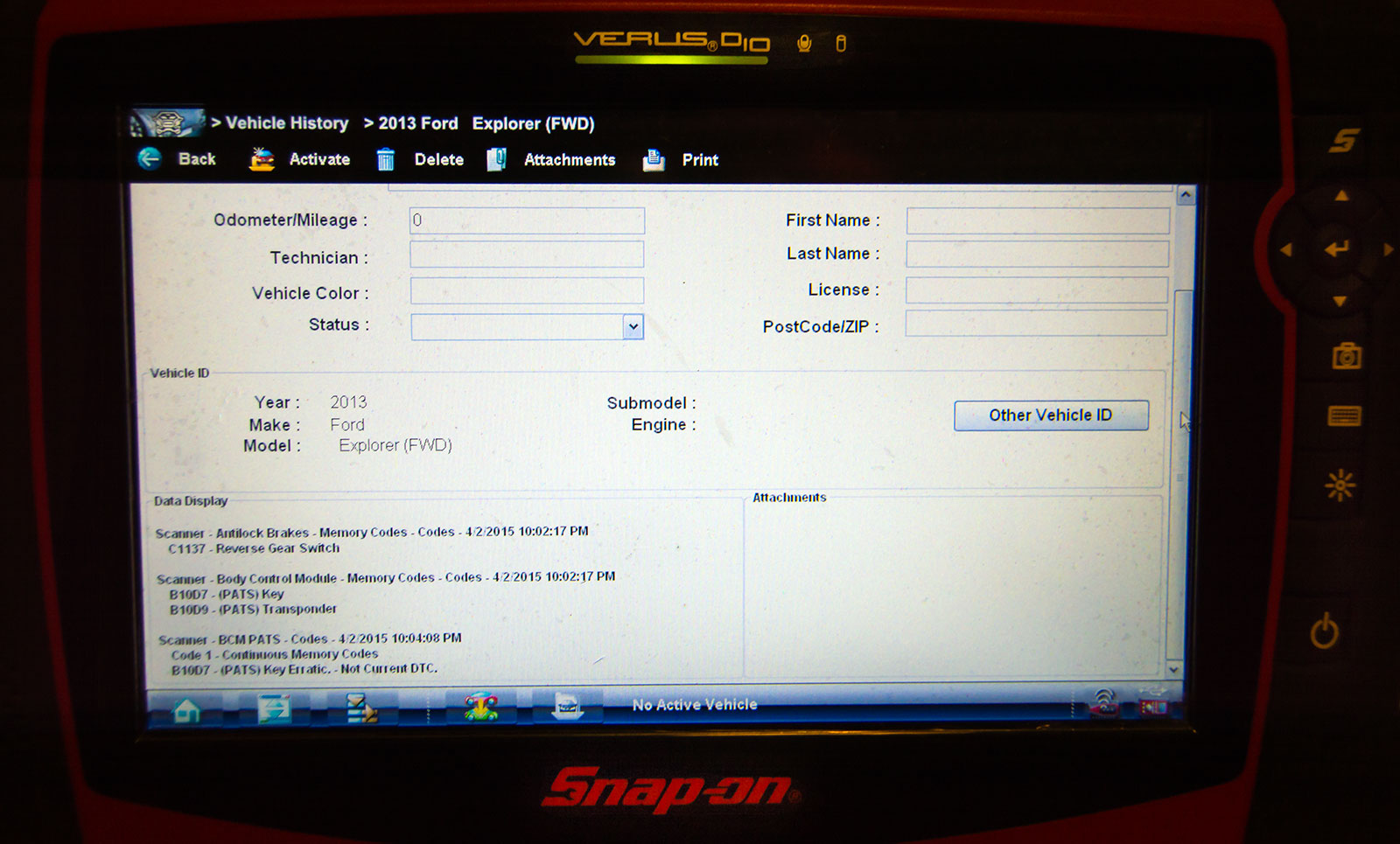
The Snap-On Verus Pro was able to read all the stored DTC information.
This one was towed in as a no start. The customer had it into another shop and they diagnosed it as a bad starter. After the starter was replaced it had the same problem. They had it towed to another shop and that shop called me to diagnose the vehicle. I do a lot of electrical work for this shop. The vehicle didn’t crank over when the key was turned to the start position. I noticed the DIC was displaying a message for a starting system fault. The other shop told the customer the vehicle didn’t have any codes. I hooked up my Snap-On Verus Pro and found 3 DTC’s in memory. 2 for the PATS anti-theft system and 1 for an ABS fault.
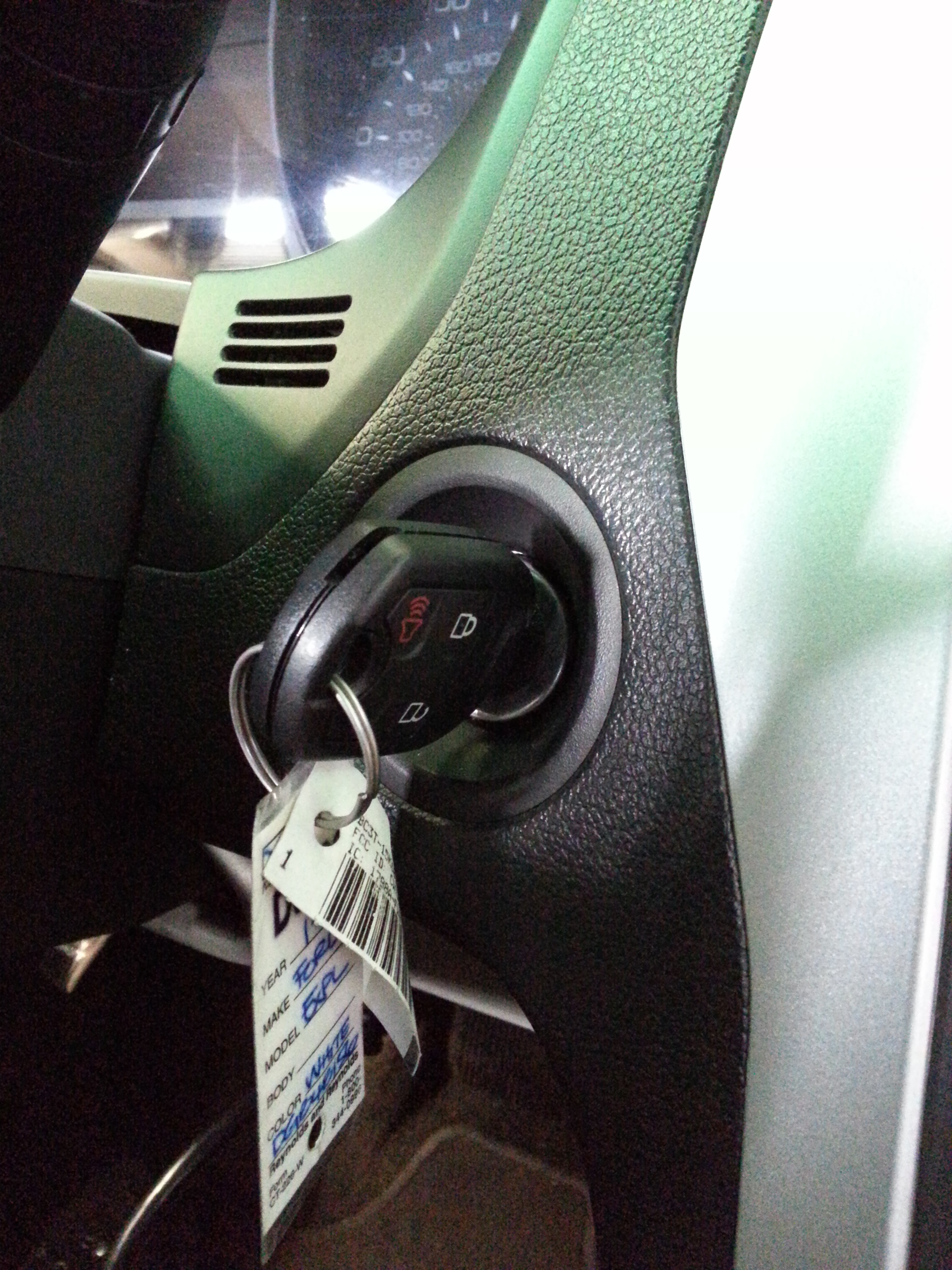
My only concerns were the 2 PATS fault DTC’s. It was necessary to hook-up my Ford factory scan tool to read the key data PID’s for the PATS system. When the key was inserted into the ignition lock cylinder the data PID never switched to key present. I had the shop call the customer to bring down the spare key to see if it was a key problem. The spare key was unable to be identified by the PATS system as well. This lead me to remove the center stack with the radio and heater controls as well as the dash speedometer cluster to gain access to the ignition switch. It was necessary to remove the ignition lock cylinder/switch assembly for testing.
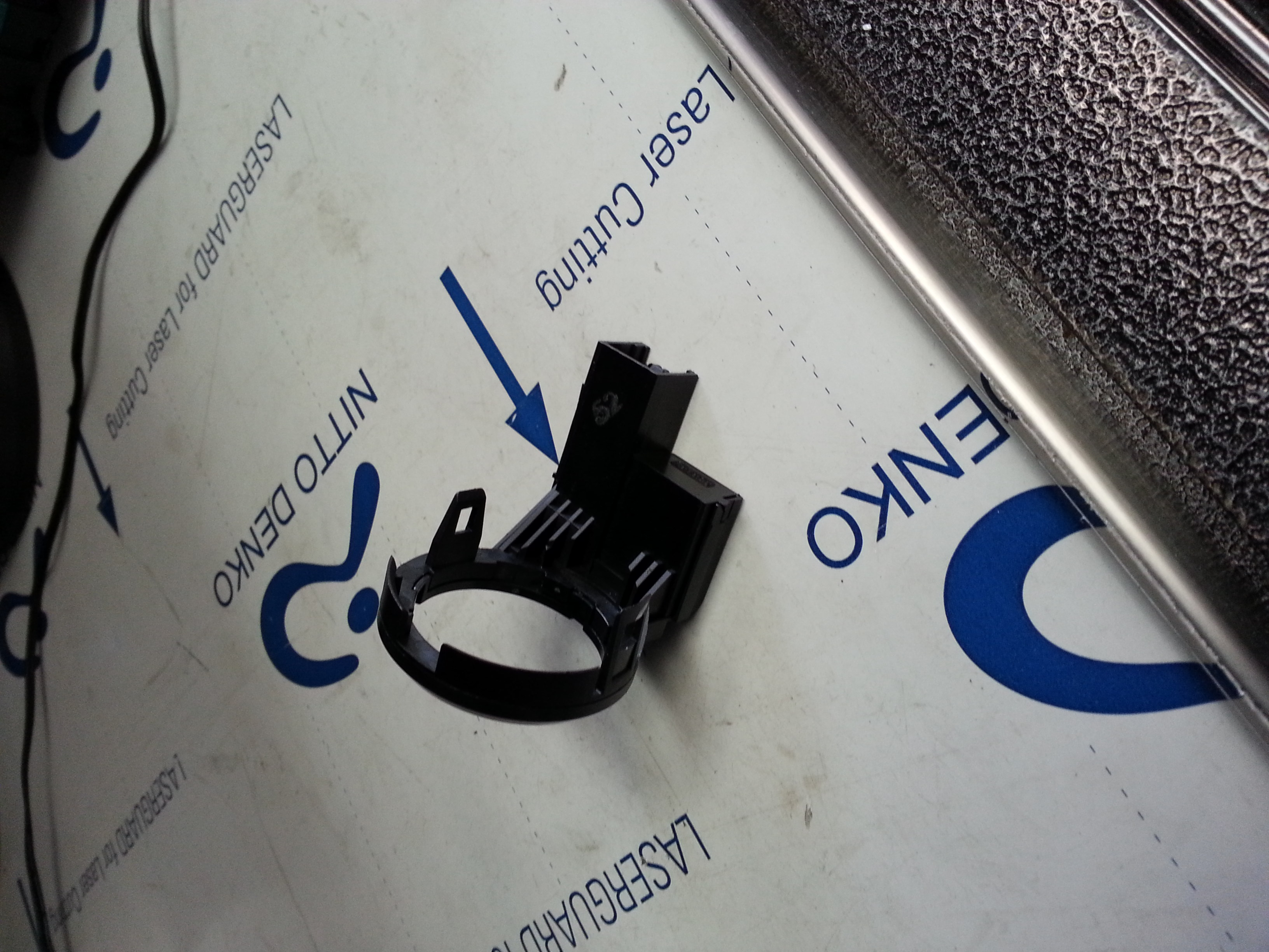
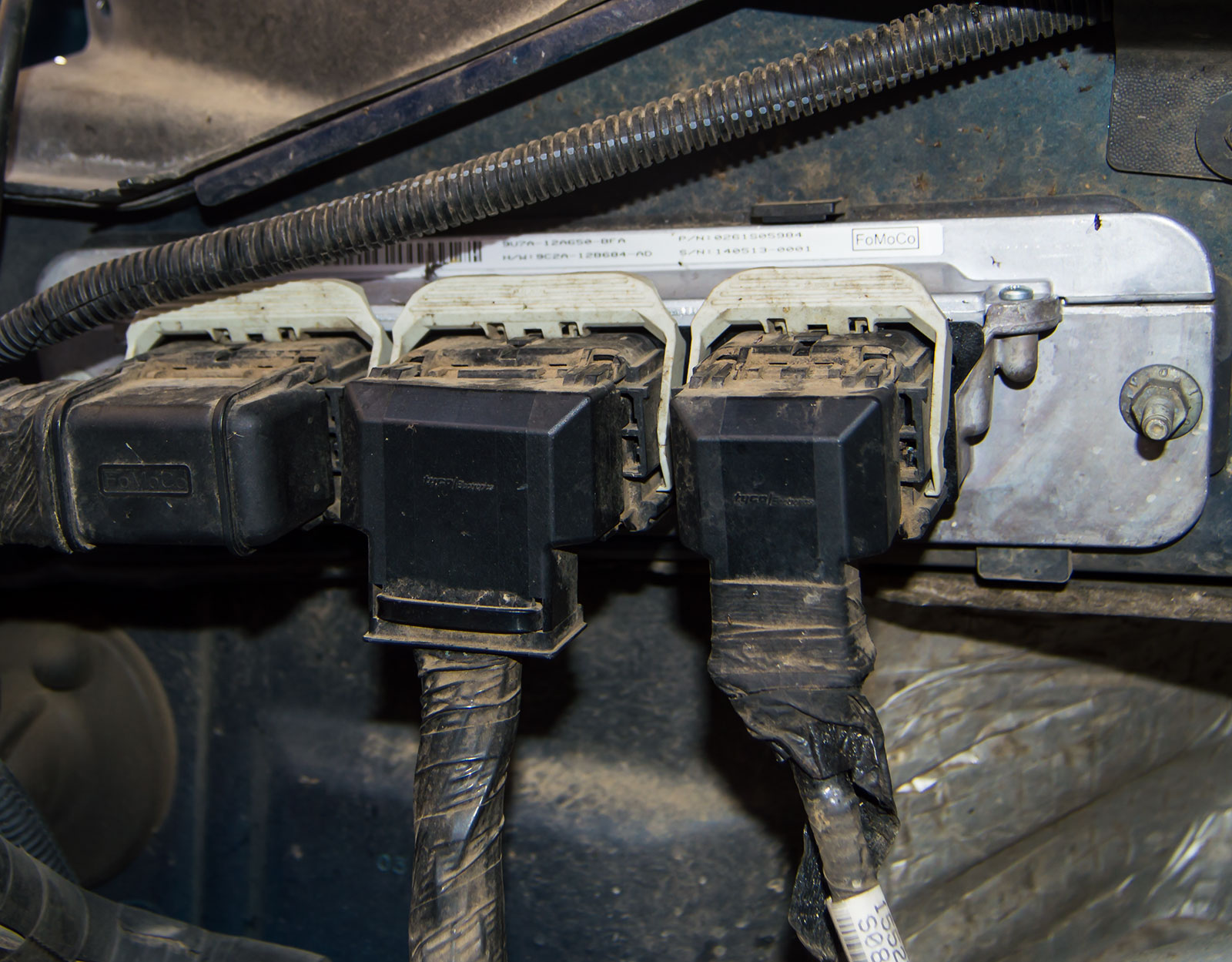
The PATS anti-theft system transceiver that reads the key’s transmitter ID information.
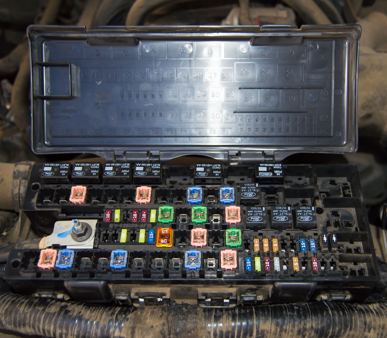
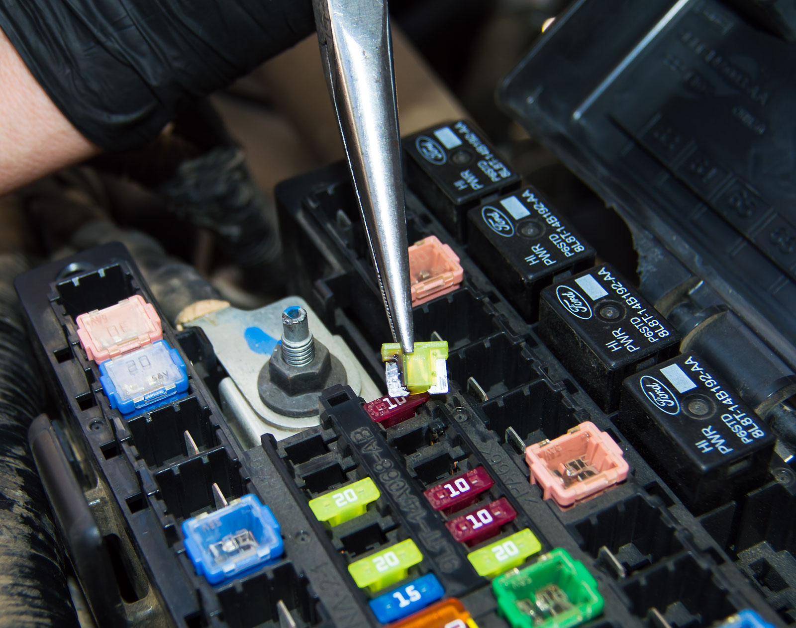
It was necessary to check fuse F18 and back probe the transceiver. This is a check for the PCM wake up request from the ignition lock cylinder when the key is inserted into the cylinder.
Both the fuse voltage and the wake up request signal were present. The next step was to verify the circuit ground. Without being able to crank the starter to load the circuit, I could only measure it with the PCM wake up command request. The ground looked good and gave correct battery voltage on the load side from the PCM.
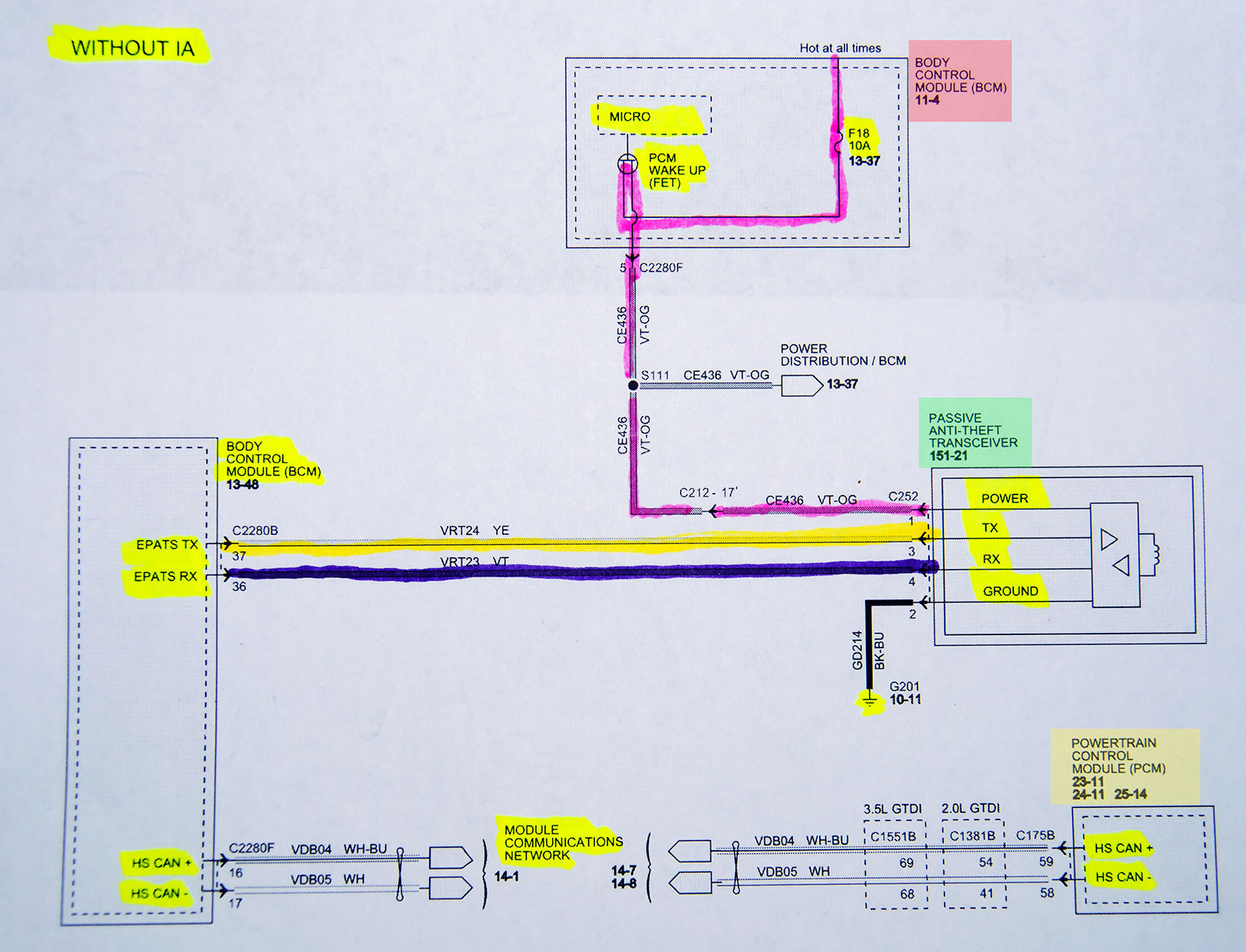
Wiring diagram for the Transceiver, BCM and PCM circuits.
Notice the lack of signal information in this schematic. It’s
yet another reason to have the proper tools and education
to properly diagnose today’s complex vehicles.
I used my Snap-On Vantage Ultra to perform a frequency test to measure a change in the signal inputs to the BCM in an attempt to check the transceiver’s ability to send the key input signal to the Body Control Module. It’s also known as the BCM.
The factory diagnostic information does not offer internal module and signal information. Without knowing what the signal actually is, I tried a few different signal tests and only managed to get the frequency signal to respond. The RX signal had no response and the TX signal had 2.60 hz output. I still didn’t know the proper signal info, but with one side unable to respond to the BCM it was necessary to order a replacement transceiver. Unfortunately, Ford and other manufacturers never give internal module control input/output signal information.
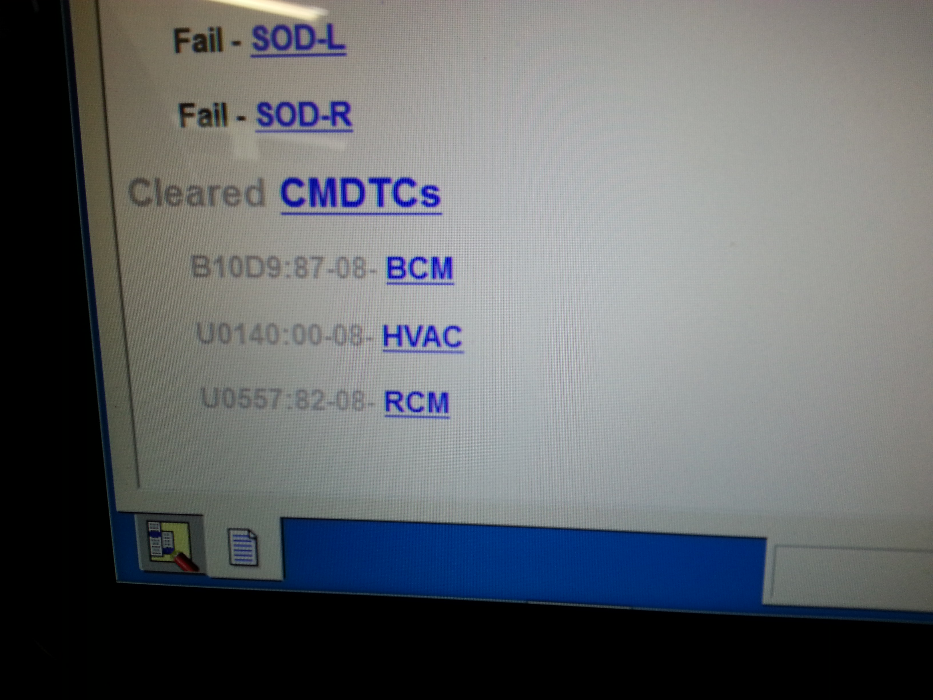
After the repairs the stored DTC’s were cleared and did not reset. This verifies that the repair is complete and the system is 100% functional.
The new Ford transceiver was delivered and installed. The data PID was able to read both keys as present and the vehicle started up without a problem. After installing the transceiver and putting everything back together, I found a PCM update available for this vehicle and the customer was okay with updating his car after fixing the no start problem.
The replacement transceiver signal was 7.85 hz on both the RX and TX circuits to the BCM. This case study will go into my fixed repair files for future information for the next one that has this problem.
After the transceiver was replaced and everything was put back together the vehicle starts and runs without any further issues.
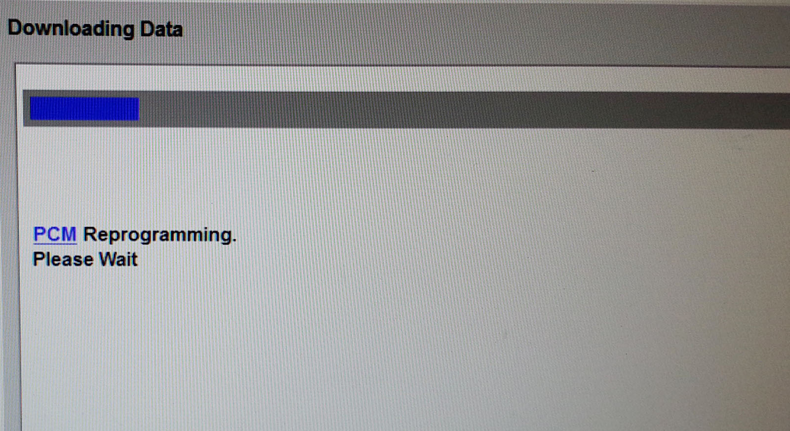
After the repairs were completed, the customer authorized a PCM update to the latest software calibrations. This insures proper vehicle operation and eliminates possible software related faults that can’t be fixed by throwing parts at it. No guesswork here!
This is another case study that shows why proper tooling is necessary to diagnose today’s computerized and high technology vehicles.
Code readers can’t give you the information required to do the job right. Throwing parts at the car is a complete waste of time and money. Don’t waste your time and money on guesswork repairs. Find a skilled technician with the proper tools and education to fix it right the first time.